QX949 IS a receiver AM/FM Stereo of PIONEER at 70s. It has 4 amplifier to processing hifi audio came from radio or any stereo input. It using 39 to 48 VDC supply simetrically.
INFO
The amplifier able to amplify the audio input became 4 x 40 Watt Audio for 8 Ohm load each.
SCHEMATIC DIAGRAM
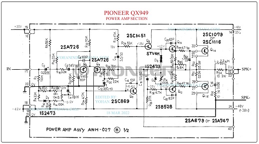
This is an edited and cropped schematic diagram of PIONEER’s QX.

The power amp use 39 to 48 VDC simetrically to make amplified audio. The Voltage is 48 VDC when there is no signal but drop to 38 VDC when it work load in maximum audio driving.
VR1 is a trimpot to setup the output of the amplifier to keep 0 VDC at output speaker .
The power amp has no use transistor servo driver . It just using biasing diode numbered STV4H and there is an trimpot to make normal biasing for final transistor.
First, the signal enters the preamplifier circuit that uses transistors Q2 and Q4.
Then this signal goes to Q6 (numbered 2SC869) or what we call Voltage Amplifier Stages.
This circuit still uses elco as a positive feedback signal boostrap to be amplified by Q6 (2SC1451).
Then the signal from this VAS will go to the Q10 Q12 driver circuit (2SD358 & 2SB528).
Finally is transistor number Q14 and Q16 (2SC1079 & 2SA679).
NOTE
2SC1079 able to make audio at 100 Watts maximum load ( SOURCE )
