HARMAN KARDON AVR25 is a Tuner Audio Video Amplifier produced by HARMAN 90s. Its contains a AM/FM Stereo Tuner, Phono Amplifier, Line /AUX amplifier, Microphone and Video Amplifier.
INFO
Front side of the amplifier.

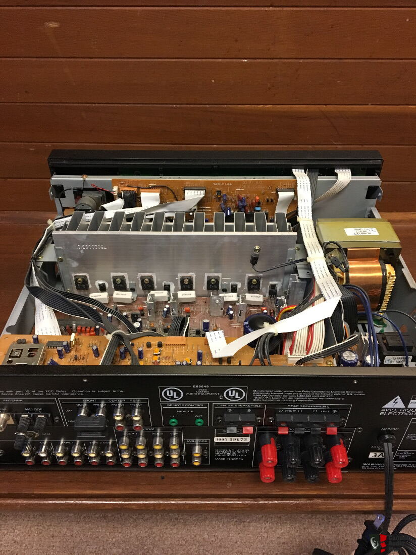
Inside of the Amplifier.
CLICK TO ENLARGE
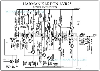
SCHEMATIC DIAGRAM
You can download the service manual from THIS VINTAGES HIFI LINK.
Its contains 72 pages and the contents are consist of Specification, Trouble shooting, Part List, and schematic diagram of the amps.
But in this article I just took a Power Amp section of the amp. This is an image after croped and some editing.

In the schematic diagram, it seems to use the Muting feature and Servo Bias features.
While the circuit block is as follows:
Preamplifier, Q251 and Q252 which use the KTA2400 transistor.
Voltage Amplifier Stage, using Q257 and Q258 ( A1024 and C3206).
Servo Bias Q270 ( C4137 ). There are no trimpot to adjust. Its fix value to limiting the voltage between the emitter resistors and the power transistors.
The Amplifier Driver uses a pair of Q260 (C4883) and Q261 (A1859).
And last: Final Power Amplifier of Q262 and Q263, using transistor numbers C3182 and A1265.
Block muting utilizes Q253 and Q254 ( A2400 and A1266 ).
INFO
With simetrically 38VDC, the amplifier able to make 130 watt every channel at 4 Ohm load. But the power transistor only generated 100 Watts at maximum power dissipation.
It means that you can not make connection between the amplifier and a 4 Ohm speaker. Just 8 Ohm usable.
KTA2400 equal with 2SC2400.
