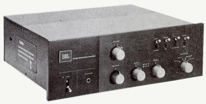
I’m wandering to the internet and came across an old JBL amp, the name of this amp is SA660 T-AMPLIFIER that make me curious about the name of this T-AMPLIFIER, especially the schematic diagam of its amplifier.
WHO JBL660
JBL = JAMES BULLOUGH LANSING.
He was born as a reliable audio technician in his era.
Born as James Martini in 1902 in Macoupin district, the state of Illinois, United States of America.
Since childhood he was smart in electrical and mechanical science.
His first company was making speakers with its name LANSING brand.
Then in 1941 became ALTEC LANSING, because the company was bought by Altec.
Then he created his own company and then he gave the name JAMES BULLOUGH LANSING, or simply “JBL”.
Unfortunately he ended up committing suicide in 1949. (wikipedia).
This SA660 amp made by JBL includes an amp by introducing the T-AMPLIFIER technique, where it has an amplification level of up to 3 levels starting from 5 audio phase separation diodes.
GENUINE SCHEMATIC
The following is a schematic cropped from the original format of the article.
The original document can be found on the internet by typing: SA660 schematic diagram.
In this schematic there is an explanation of the principle of the tool and the components used in it.
According to the reviewer’s website, the specs for this amp are as follows:
- Power output: 60 watts per channel into 8Ω (stereo)
- Frequency response: 20Hz to 20kHz
- THD : 0.2%
- Damping factor: 23
- Input sensitivity: 4mV (MM), 250mV (line)
- Signal to noise ratio: 72dB (MM), 85dB (line)
- Speaker load impedance: 4Ω to 16Ω

The manual said that this amp uses 3 different supply voltages, its 41.5VDC, 46.5VDC, and 52VDC.
All the voltage are symmetrical.
However, to make it easier to clone the schematic of this amp, I tried to venture to make just one.
Unfortunately the name of the transistor in this schematic was unknown.
It uses the JBL version of the PART NUMBER instead of the usual part numbers.
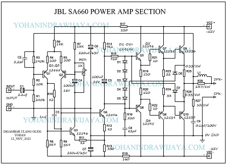
RE-DRAWING SCHEMATIC AND MODIFIED COMPONENT
Then I re-draw this component using PROTEUS and PAINT software. The result is as follow:

NOTE
Elco which has no working voltage are uses a working voltage of 50V.
All resistors are 0.5 Watt unless it is explained in the schematic.
D1 to D5 use 1N4148, for protectors D6, D7 use the number 1N4002.
For the inductor of the output , use wire winding by 0.7 diameter wire 20 times.
The function of the trimpot in the input circuit is for determining DC 0 Volts.
The replacement transistors I recommend are:
- Q1,Q2 = A564
- Q3,Q4 = D438
- Q5= BD139
- Q6 = BD140
- Q7 = TIP31
- Q8 = TIP32
- Q9 = TIP3055
- Q10 = TIP2955
See the video review below:


Thank you for writing this post. I like the subject too.
Thanks for any other magnificent article. Where else may anyone get that kind
of information in such an ideal method of writing? I have a presentation subsequent week, and I am at the search for such info.