The SA706 is a PIONEER stereo amplifier made in the 70s that has an amplifer output of up to 60 Watts at 8 Ohm loads.
INFO
This amplifier uses tone control by utilizing the feedback power amplifier, and not like the tone control circuit that we usually know in Indonesia.
PCB kits and tone control schematics that we usually encounter are using the principle of passive tone control (only R and C networks) and a Baxandall feedback system.
We’re also often encounter Parametric tone control, but it’s still out of trend than what I mention earlier
SKEMA
The service manual for this amp is quite long. Its explains the working principle of the circuit, circuit features, bill of materials and amplifier schematic which split into several pages.
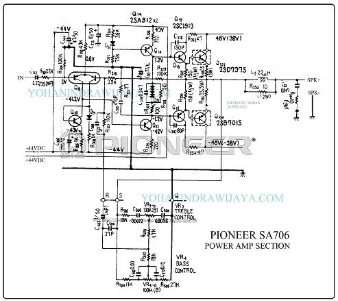
To make the review easier, I just took the power amplifier scheme for collection and review.
The following is a schematic of the cropped and edited result of this SA706 amp.
CLIK TO ENLARGE

From this schematic, you can see several things, including the power supply 48VDC when there is no load and becomes 38VDC when full load.
This power amplifier uses 4 levels, starting from the initial amplifier with differential system, voltage amplifier stage, driver amplifier and final power amplifier.
Firstly, Differential amplifier Q8 uses transistor number 2SA798.
Secondly, Voltage amplifier Q12 and Q14 using transistor numbers A912 and C1885.
Thirdly, Driver amplifier Q16 and Q18 use transistor numbers A913 and C1913.
And Last, Final Power Amplifier uses transistor numbers D737S and B701S.
NOTE
The working voltage in the schematic is 48VDC at no load and 38VDC at full load.
This means that the output of this amplifier is still able of producing an higest output voltage of 23 Vrms at the load 8 Ohm speaker.
Transistors 2SD737S and 2SB701S are able of producing a maximum power of up to 125 Watts ( SOURCE ).


